
About us / Archive
From the drawing board to software
The story of design documentation, CAD programs and the tools that shaped our work.
At the start of my engineering career, I learned that documentation is an important part of an electrical installation. Fresh from graduating with honours, I spent two years “carrying the bag” for Ferdinand Marx, the power distribution foreman in the energy department. Although I naturally complained at the time, that practical experience shaped my whole career. I owe thanks to him and to František Štindl, the electrical maintenance supervisor who introduced me to office work and the drawing board.
The roots of design work at EpS therefore go back to around 1983, when the first fragments of what could be called electrical documentation appeared. I later became head of the power distribution department, but design remained the work I enjoyed most.
Like many people in the profession, I started by following established examples. EZ Praha was then a leading company in energy engineering. I tried to emulate its designs, whose documentation already had a clear structure and proven rules. I learned that a project should ideally contain:
- Technical report
- Bill of materials
- Cable schedule
- Single-line diagrams
- Circuit diagrams
- Wiring diagrams
- Construction drawings
- Layout drawings
I always tried to achieve that ideal. We first agreed the single-line diagrams, sketched the circuit diagrams and, after approval, produced the wiring diagrams. Construction and layout drawings developed alongside them. The almost-complete project then “only” needed tracing in ink, with the technical report, material lists and cable schedules added. Despite our best efforts, errors could be present from the outset. The labour involved encouraged shortcuts, such as using one standard diagram for several drives. Differences were added as variants a), b), c), until it became difficult to know what belonged where. Changes after delivery rarely reached every document; even keeping circuit and wiring diagrams current was hard. We cut tracing sheets apart and inserted blank sections with transparent paper tape, repeatedly scraping away obsolete details with a razor blade.
I therefore welcomed the initiative from Chemoprojekt in Písek, from whom we bought “ELCAD”, an adaptation of OrCAD for general electrical drawings. By today’s standards it was not easy to use, but it eliminated tracing paper and ink.
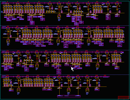
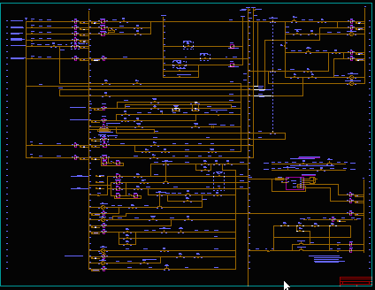
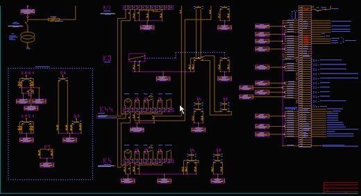
The drawings looked like this:
Single-line diagram
Circuit diagram
Wiring diagram
Circuit diagram
Wiring diagram
ELCAD’s great advantage was printing large drawings on A4 or A3 printers. The overlapping sheets could be cut and joined into an A0 drawing, even with an imperfect cut. Rotated text was difficult, and circles were drawn as hexagons. Macros, a symbol library and good speed on contemporary PCs were advantages. I used it actively from 1990 to 1994.
As software improved, I reviewed the options again and chose DesignCAD version 6 for DOS, sold with a Czech manual by ENERGOPROJELT Praha a.s. It was excellent software with very capable electrical drawing tools. There were some Czech font issues; this manual is what remains:
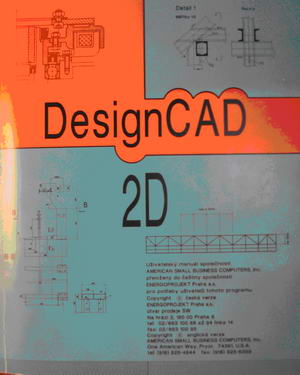
Windows was becoming dominant and promising a great deal, so we bought DesignCAD 7. I was still able to run this version; here are some screenshots:
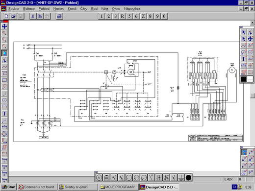
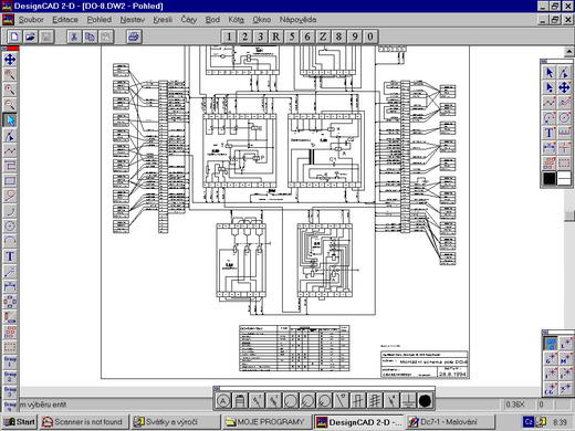
Version 7 may not have been as polished as version 6 under DOS, but the common Windows environment, clipboard and fonts were a real step forward. Drawing, working to scale and graphic formatting had become very capable. ARCADEA supplied the product, a Czech manual and telephone support.
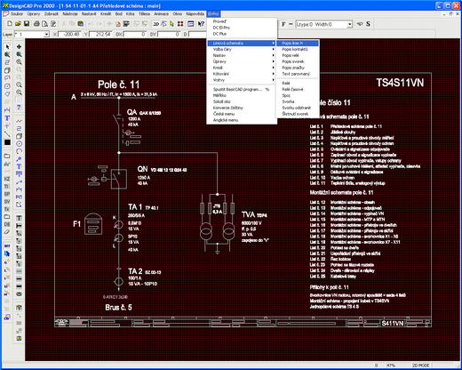
It was still essentially a drawing tool. We wanted productivity beyond electronic drafting and found it in the DC El-Pro extension from 3Z Systéms, purchased with DesignCAD 2000. Its developer, Ing. Zavadil, listened to customer needs and added functions. In 1999 we used it for the České Budějovice Střed 22 kV substation project, comprising around 580 drawings. The extension printed entire directories automatically. When protection relay types changed near completion, we could modify the first drawing and let the program find and update the other files. This was when many users of the most widespread CAD system were not yet working with several open drawings at once. The platform also produced the large enclosed 22 kV and 6 kV switchgear projects at Plav and Škoda Plzeň.
In 2001 we bought DesignCAD 3D MAX for its promised raster-image features. However, it handled the drawing grid differently, so we continued with DC2000 and DC El-Pro. Various DesignCAD versions were our main tools from 1994 to 2002, and we were still using it as supplementary software when this account was written.
Example from DC2000 with DC El-Pro:
At the beginning of 2002, it was time to choose new software again. This time it had to be purpose-built for electrical engineering, with reliable bills of materials and checks of coil-to-contact cross-references. These were weak points in DesignCAD. Material lists could be generated, but Excel was often easier, with the resulting risk of mistakes. Splitting lists by individual component and location, and separately by type and manufacturer, was particularly difficult. Installation companies needed both: the installer needed the parts for a particular switchboard bay, while purchasing needed totals by type and manufacturer. Both lists had to contain identical quantities and components.
In May 2002 we bought PC Schematic Elautomation. It was exactly what we needed. The Danish product had Czech support through CADWARE. Ing. Klauz handled distribution, localisation and support and listened to suggestions, giving us a route for customer ideas to reach the manufacturer.
The structure of EpS projects at the time:
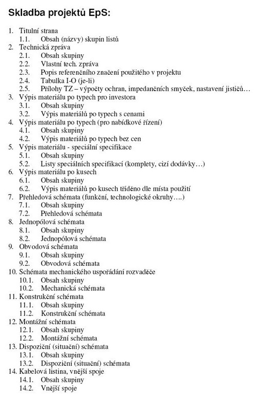
A few examples from a typical project structure:
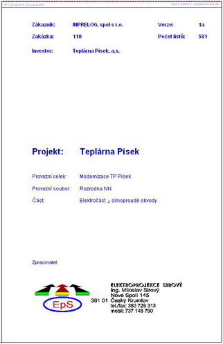
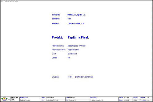
Title page:
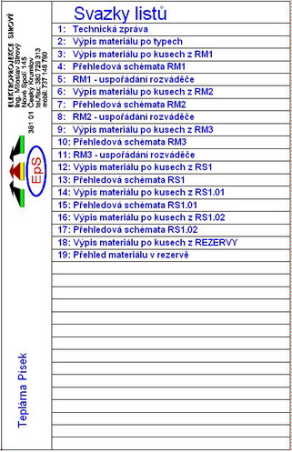
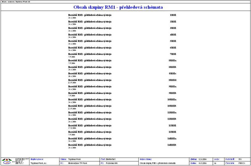
Contents of the drawing groups:
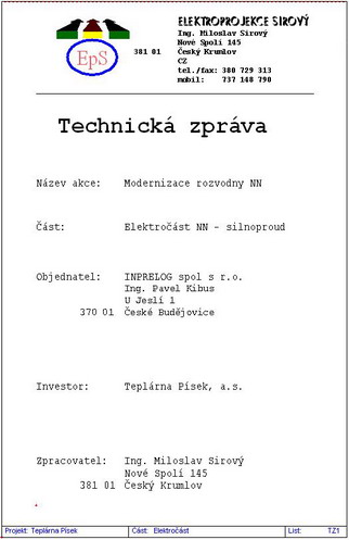
Technical report:
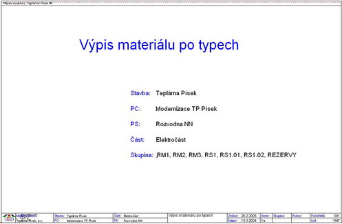
Bill of materials by type:
Supplier contacts:
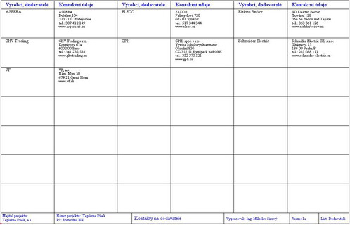
Itemised bill of materials:
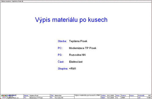
Group title page:
Each title page is followed by the group’s contents:
The individual circuit diagrams, wiring diagrams and other drawings follow.
The switchboard component layout is worth showing. Entering the switchboard and bay number automatically generates front views of the associated equipment:
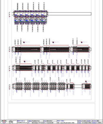
The components then only need arranging to fit the enclosure. The program offers many such automated features. For a practice covering a wide range of electrical documentation, its versatility matters: from building installations to PLCs. Speed, stability and the size of a complete project in one file were also impressive. Internal ZIP compression reduced the example project of 590 pages in A4, A3 and 4×A3V formats to just 1.5 MB, almost fitting on a floppy disk. Enough about the product; the important point is to treat design documentation as:
part of the electrical installation, and to handle it accordingly.